Basic Electronics Course in Pakistan


Basic Electronics Course
This is the BEST basic electronics course in Pakistan on the internet. Why? Because it is organized so you can select your areas of interest and go directly to them. Most internet courses are disorganized and it is hard to find particular information and follow their train of thought. There is a lot of good information on the internet but finding it and organizing it takes a lot of time, skill and effort. We have done all that for you. Enjoy. Whatever your interest or current level of knowledge you can find valuable information here in our interesting electronics course. If you are a rank beginner or have a post-doctorate in electrical engineering you can find informative material in our course.
Getting started with basic electronics is easier than you might think. This Pakluck will hopefully demystify the basics of electronics so that anyone with an interest in building circuits can hit the ground running. This is a quick overview into practical electronics and it is not my goal to delve deeply into the science of electrical engineering. If you are interested in learning more about the science of basic electronics, Wikipedia is a good place to start your search. Basic Electronics Course in Pakistan..
In This Course?👇
Learn About AC or DC Current
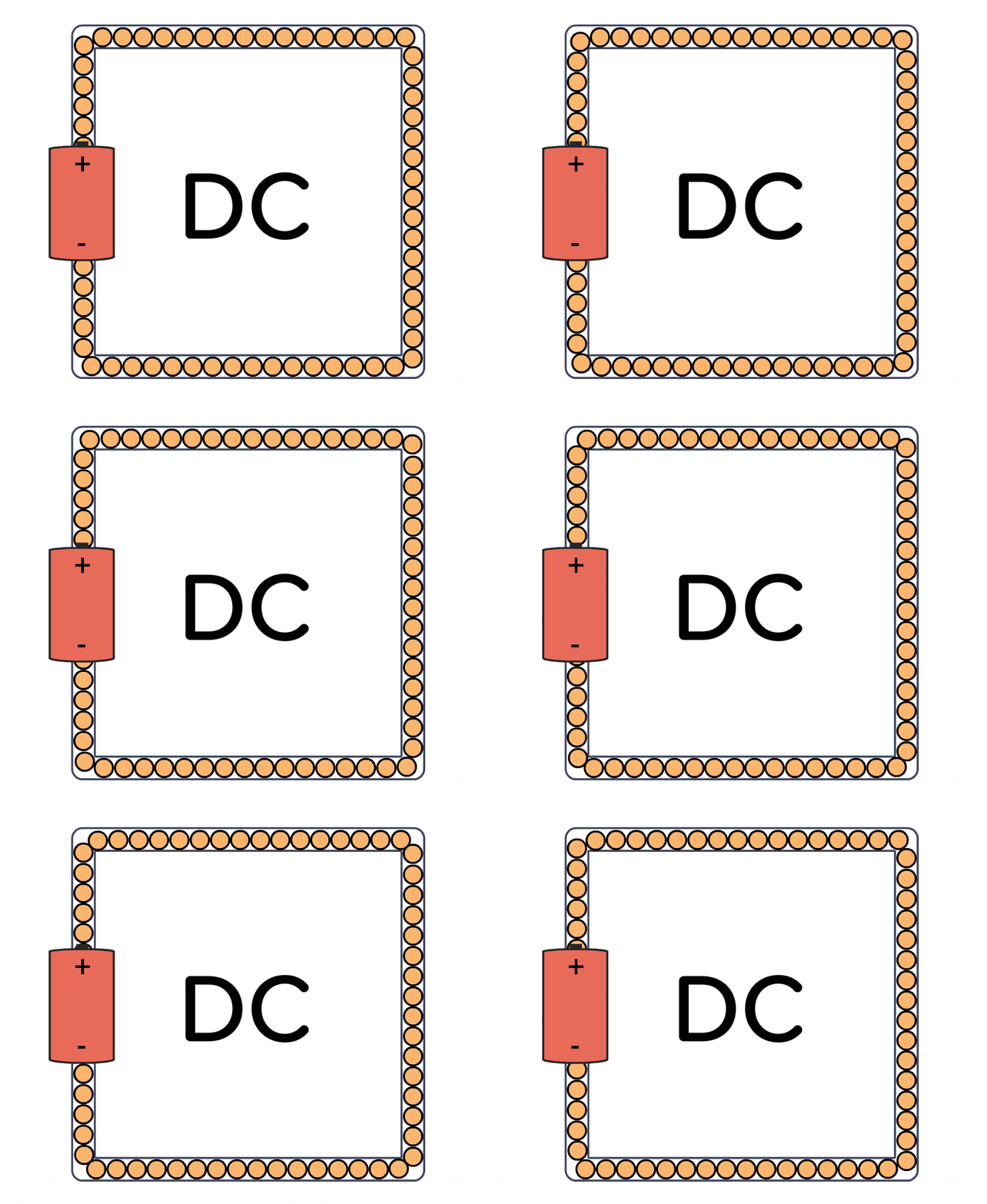
There are two types of electrical signals, those being alternating current (AC), and direct current (DC).
With alternating current, the direction of electricity flows throughout the circuit is constantly reversing. You may even say that it is an alternating direction. The rate of reversal is measured in Hertz, which is the number of reversals per second. So, when they say that the US power supply is 60 Hz, what they mean is that it is reversing 120 times per second (twice per cycle). Basic Electronics Course in Pakistan
About Circuits

A circuit is a complete and closed path through which electric current can flow. In other words, a closed circuit would allow the flow of electricity between power and ground. An open circuit would break the flow of electricity between power and the ground.
Resistance

For instance, in the circuit above, the motor that electricity is flowing through is adding resistance to the flow of electricity. Thus, all of the electricity passing through the circuit is being put to use.
In other words, there needs to be something wired between positive and ground that adds resistance to the flow of electricity and uses it up. If a positive voltage is connected directly to the ground and does not first pass through something that adds resistance, like a motor, this will result in a short circuit. This means that the positive voltage is connected directly to the ground. Basic Electronics Course in Pakistan
Series Vs. Parallel
There are two different ways in which you can wire things together called series and parallel.
When things are wired in series, things are wired one after another, such that electricity has to pass through one thing, then the next thing, then the next, and so on.
In the first example, the motor, switch and battery are all wired in series because the only path for electricity to flow is from one to the next, and to the next.
When things are wired in parallel, they are wired side by side, such that electricity passes through all of them at the same time, from one common point to another common point
In the next example, the motors are wired in parallel because the electricity passes through both motors from one common point to another common point.
in the final example, the motors are wired in parallel, but the pair of parallel motors, switch and batteries are all wired in series. So, the current is split between the motors in a parallel fashion but still must pass in series from one part of the circuit to the next.
Basic Components

In order to build circuits, you will need to become familiar with a few basic components. These components may seem simple but are the bread and butter of most electronics projects. Thus, by learning about these few basic parts, you will be able to go a long way. Basic Electronics Course in Pakistan
Resistors

As the name implies, resistors add resistance to the circuit and reduce the flow of electrical current. It is represented in a circuit diagram as a pointy squiggle with a value next to it.
The different markings on the resistor represent different values of resistance. These values are measured in ohms.
Resistors also come with different wattage ratings. For most low-voltage DC circuits, 1/4-watt resistors should be suitable.
You read the values from left to right towards the (typically) gold band. The first two colors represent the resistor value, the third represents the multiplier, and the fourth (the gold band) represents the tolerance or precision of the component. You can tell the value of each color by looking at a resistor color value chart.
Or… to make your life easier, you could simply look up the values using a graphical resistance calculator.
Anyhow… a resistor with the markings brown, black, orange, and gold will translate as follows:
1 (brown) 0 (black) x 1,000 = 10,000 with a tolerance of +/- 5%
Any resistor of over 1000 ohms is typically shorted using the letter K. For instance, 1,000 would be 1K; 3,900, would translate to 3.9K; and 470,000 ohms would become 470K.
Values of ohms over a million are represented using the letter M. In this case, 1,000,000 ohms would become 1M.
Capacitors
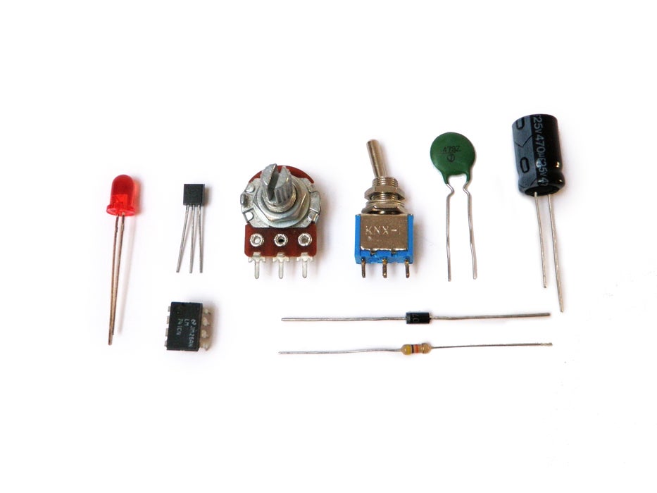
A capacitor is a component that stores electricity and then discharges it into the circuit when there is a drop in electricity. You can think of it as a water storage tank that releases water when there is a drought to ensure a steady stream.
Capacitors are measured in Farads. The values that you will typically encounter in most capacitors are measured in picofarad (pF), nano farad (nF), and microfarad (uF). These are often used interchangeably and it helps to have a conversion chart at hand.
The most commonly encountered types of capacitors are ceramic disc capacitors that look like tiny M&Ms with two wires sticking out of them and electrolytic capacitors that look more like small cylindrical tubes with two wires coming out the bottom (or sometimes each end).
Ceramic disc capacitors are non-polarized, meaning that electricity can pass through them no matter how they are inserted into the circuit. They are typically marked with a number code that needs to be decoded. Instructions for reading ceramic capacitors can be found here. This type of capacitor is typically represented in a schematic as two parallel lines.
Electrolytic capacitors are typically polarized. This means that one leg needs to be connected to the ground side of the circuit and the other leg must be connected to power. If it is connected backward, it won’t work correctly. Electrolytic capacitors have the value written on them, typically represented in uF. They also mark the leg which connects to the ground with a minus symbol (-). This capacitor is represented in a schematic as a side-by-side straight and curved line. The straight line represents the end that connects to power and the curve connected to the ground.
Diodes

Diodes are components that are polarized. They only allow electrical current to pass through them in one direction. This is useful in that it can be placed in a circuit to prevent electricity from flowing in the wrong direction.
Another thing to keep in mind is that it requires energy to pass through a diode and this results in a drop in voltage. This is typically a loss of about 0.7V. This is important to keep in mind for later when we talk about a special form of diode called LEDs.
The ring found on one end of the diode indicates the side of the diode which connects to the ground. This is the cathode. It then follows that the other side connects to power. This side is the anode.
The part number of the diode is typically written on it, and you can find out its various electrical properties by looking up its datasheet.
They are represented in the schematic as a line with a triangle pointing at it. The line is that side connected to the ground and the bottom of the triangle connects to power.
Transistors

A transistor takes in a small electrical current at its base pin and amplifies it such that a much larger current can pass between its collector and emitter pins. The amount of current that passes between these two pins is proportional to the voltage being applied at the base pin.
There are two basic types of transistors, which are NPN and PNP. These transistors have opposite polarity between the collector and emitter. For a very comprehensive intro to transistors check out this page.
NPN transistors allow electricity to pass from the collector pin to the emitter pin. They are represented in a schematic with a line for a base, a diagonal line connecting to the base, and a diagonal arrow pointing away from the base.
PNP transistors allow electricity to pass from the emitter pin to the collector pin. They are represented in a schematic with a line for a base, a diagonal line connecting to the base, and a diagonal arrow pointing toward the base.
Transistors have their part number printed on them and you can look up their datasheets online to learn about their pin layouts and their specific properties. Be sure to take note of the transistor’s voltage and current rating as well.
Integrated Circuits (IC)

An integrated circuit is an entire specialized circuit that has been miniaturized and fit onto one small chip with each leg of the chip connecting to a point within the circuit. These miniaturized circuits typically consist of components such as transistors, resistors, and diodes.
For instance, the internal schematic for a 555 timer chip has over 40 components in it.
Like transistors, you can learn all about integrated circuits by looking up their datasheets. On the datasheet, you will learn the functionality of each pin. It should also state the voltage and current ratings of both the chip itself and each individual pin.
Integrated circuits come in a variety of different shapes and sizes. As a beginner, you will be mainly working with DIP chips. These have pins for through-hole mounting. As you get more advanced, you may consider SMT chips which are surface mount soldered to one side of a circuit board.
The round notch on one edge of the IC chip indicates the top of the chip. The pin to the top left of the chip is considered pin 1. From pin 1, you read sequentially down the side until you reach the bottom (i.e. pin 1, pin 2, pin 3..). Once at the bottom, you move across to the opposite side of the chip and then start reading the numbers up until you reach the top again.
Keep in mind that some smaller chips have a small dot next to pin 1 instead of a notch at the top of the chip.
There is no standard way that all ICs are incorporated into circuit diagrams, but they are often represented as boxes with numbers in them (the numbers representing the pin number). Basic Electronics Course in Pakistan
Potentiometers (Variable Resistor)

Potentiometers are variable resistors. In plain English, they have some sort of knob or slider that you turn or push to change resistance in a circuit. If you have ever used a volume knob on a stereo or a sliding light dimmer, then you have used a potentiometer.
Potentiometers are measured in ohms like resistors, but rather than having color bands, they have their value rating written directly on them (i.e. “1M”). They are also marked with an “A” or a “B, ” which indicated the type of response curve it has.
Potentiometers marked with a “B” have a linear response curve. This means that as you turn the knob, the resistance increases evenly (10, 20, 30, 40, 50, etc.). The potentiometers marked with an “A” have a logarithmic response curve. This means that as you turn the knob, the numbers increase logarithmically (1, 10, 100, 10,000, etc.)
Potentiometers have three legs to create a voltage divider, which is basically two resistors in a series. When two resistors are put in series, the point between them is a voltage that is a value somewhere between the source value and ground.
For instance, if you have two 10K resistors in series between power (5V) and ground (0V), the point where these two resistors meet will be half the power supply (2.5V) because both of the resistors have identical values. Assuming this middle point is actually the center pin of a potentiometer, as you turn the knob, the voltage on the middle pin will actually increase towards 5V or decrease toward 0V (depending on which direction you turn it). This is useful for adjusting the intensity of an electrical signal within a circuit (hence its use as a volume knob).
This is represented in a circuit as a resistor with an arrow pointing toward the middle of it.
If you only connect one of the outer pins and the center pin to the circuit, you are only changing the resistance within the circuit and not the voltage level on the middle pin. This too is a useful tool for circuit building because often you just want to change the resistance at a particular point and not create an adjustable voltage divider.
This configuration is often represented in a circuit as a resistor with an arrow coming out of one side and looping back in to point toward the middle.
LEDs

LED stands for the light emitting diode. It is basically a special type of diode that lights up when electricity passes through it. Like all diodes, the LED is polarized and electricity is only intended to pass through in one direction.
There are typically two indicators to let you know what direction electricity will pass through and LED. The first indicator is that the LED will have a longer positive lead (anode) and a shorter ground lead (cathode). The other indicator is a flat notch on the side of the LED to indicate the positive (anode) lead. Keep in mind that not all LEDs have this indication notch (or that it is sometimes wrong).
Like all diodes, LEDs create a voltage drop in the circuit but typically do not add much resistance. In order to prevent the circuit from shorting, you need to add a resistor in series. To figure out how large of a resistor you need for optimum intensity, you can use this online LED calculator to figure out how much resistance is needed for a single LED. It is often good practice to use a resistor that is slightly larger in value than what is returned by the calculator.
You may be tempted to wire LEDs in series, but keep in mind that each consecutive LED will result in a voltage drop until finally there is not enough power left to keep them lit. As such, it is ideal to light up multiple LEDs by wiring them in parallel. However, you need to make certain that all of the LEDs have the same power rating before you do this (different colors often are rated differently).
LEDs will show up in a schematic as a diode symbol with lightning bolts coming off of it, to indicate that it is a glowing diode.
Switches

A switch is basically a mechanical device that creates a break in a circuit. When you activate the switch, it opens or closes the circuit. This is dependent on the type of switch it is.
Normally open (N.O.) switches close the circuit when activated.
Normally closed (N.C.) switches open the circuit when activated.
As switches get more complex they can both open one connection and close another when activated. This type of switch is a single-pole double-throw switch (SPDT).
If you were to combine two SPDT switches into one single switch, it would be called a double-pole double-throw switch (DPDT). This would break two separate circuits and open two other circuits, every time the switch was activated. basic electronics course in Lahore.
Batteries
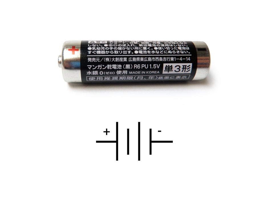
A battery is a container that converts chemical energy into electricity. To over-simplify the matter, you can say that it “stores power.”
By placing batteries in series you are adding the voltage of each consecutive battery, but the current stays the same. For instance, a AA battery is 1.5V. If you put 3 in series, it would add up to 4.5V. If you were to add a fourth in the series, it would then become 6V.
By placing batteries in parallel the voltage remains the same, but the amount currently available doubles. This is done much less frequently than placing batteries in series and is usually only necessary when the circuit requires more current than a single series of batteries can offer.
It is recommended that you get a range of AA battery holders. For instance, I would get an assortment that holds 1, 2, 3, 4, and 8 AA batteries.
Batteries are represented in a circuit by a series of alternating lines of different lengths. There are also additional markings for power, ground and voltage rating. Basic Electronics Course in Pakistan
Breadboards

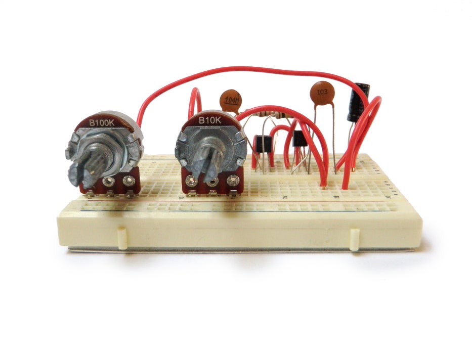
Breadboards are special boards for prototyping electronics. They are covered with a grid of holes, which are split into electrically continuous rows.
In the central part there are two columns of rows that are side-by-side. This is designed to allow you to be able to insert an integrated circuit into the center. After it is inserted, each pin of the integrated circuit will have a row of electrically continuous holes connected to it.
In this way, you can quickly build a circuit without having to do any soldering or twisting wires together. Simply connect the parts that are wired together into one of the electrically continuous rows.
On each edge of the breadboard, there typically run two continuous bus lines. One is intended as a power bus and the other is intended as a ground bus. By plugging power and ground respectively into each of these, you can easily access them from anywhere on the breadboard.
Let’s Design interesting Circuits
Who should attend:
Students who have technical knowledge and interest, are eligible for this program. Hobbyists who do not have knowledge of embedded systems and robotics but wish to learn can also pursue this program.
Career Aspects:
Senior Robotic System Engineer, Embedded Engineer, Product lead, Predictive Analytics, Robotics & Embedded System Trainer.
Industry Needs:
Rapid development and knowledge of basic electronics courses in Pakistan add to the electronic requirement standards. Be it a small device or a car, microcontrollers and development boards are used all over.
Join our Course and learn about Basic Electronics Course and Design different types of circuits. If you want to become a Robotic Developer Join our Arduino Course and learn about basic programming and develop your own robot..
We also offer different types of courses like WordPress Course, Digital Marketing Course, SEO Course, Programming Course, and Social Media Marketing Course.
If you join any Course Pakluck offer the Best Short Courses in Pakistan, Basic Electronics Course in Pakistan








EXCELLENT
thanku so much for your best convanion